


What is a dry type transformer 3-phase
You can define a 3 phase dry type transformer as a static electromagnetic device. This equipment transfers alternating current power between electrical circuits through magnetic induction. You will notice that the system operates continuously without moving parts.
Unlike traditional liquid-filled units, this device functions completely without oil or liquid coolant. Instead, the system relies on simple ambient air circulation and solid insulation systems to cool internal components safely.
Power distribution networks depend on this technology for one clear purpose. The equipment steps up or steps down voltage levels efficiently. Therefore, you can deliver safe electrical power across your industrial facility or commercial building.
Key Takeaways
A 3 phase dry type transformer changes voltage levels safely using air and solid insulation instead of oil.
Engineers build these units as cast resin or vacuum pressure impregnated models to match different environment needs.
Facilities install dry-type transformers indoors because these machines prevent fires and eliminate oil leaks.
Building owners save money over time through low maintenance needs and easy installation steps.
What Is a 3 Phase Dry Type Transformer?
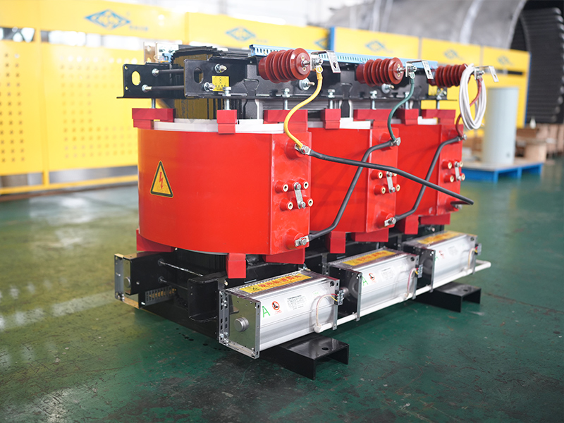
You can understand a 3 phase dry type transformer by examining its core components and silent operation. This device uses static electromagnetic force to convert energy. It transfers continuous power across circuits without any moving parts.
Core Working Principle and Windings
A standard 3 phase dry type transformer uses six individual windings positioned around a laminated steel core. You will find three primary windings and three secondary windings in this layout. Engineers configure these sets in star (Y) or delta (Δ) patterns to manage system voltages.
The system transfers energy through a clear four-step process:
Excitation and Flux Generation: You apply balanced three-phase voltages to the primary windings. This action creates alternating magnetic fluxes in the core legs, each offset by a 120° phase difference.
Magnetic Path Balance: The combined vector sum of these three-phase fluxes equals roughly zero. This condition creates a closed magnetic circuit that minimizes energy losses.
Induction: The alternating flux in each limb intersects the primary and secondary windings. This movement induces an electromotive force based on the primary-to-secondary turns ratio.
Power Delivery: Output voltages on the secondary side combine via star or delta connections to deliver balanced electrical power.
You calculate apparent power in these systems using the formula S = 1.732 x V x I. In this equation, S represents apparent power, V denotes line-to-line voltage, and I indicates line current. The core material also directly affects overall efficiency. Narrow B-H hysteresis loops reduce energy dissipation during operation.
Core Material | Magnetic Characteristics | Core Loss Behavior | Primary Application |
|---|---|---|---|
Grain-Oriented Silicon Steel | High magnetic permeability aligned directionally | Reduced hysteresis dissipation | Industrial and distribution units |
Amorphous Alloy | Superior efficiency in magnetic transfer | Superior reduction in core losses | High-efficiency distribution units |
Solid Insulation and Cooling Systems
Solid insulation replaces traditional transformer oil in these units. Manufacturers use tough materials like Epoxy resin, Nomex®, fiberglass, and mica systems to protect internal components. These solid materials allow safe indoor operation without any oil-leak risks.
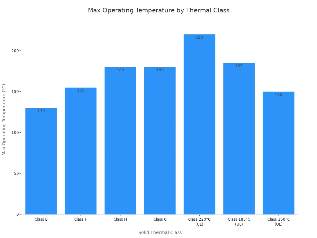
Different solid insulation thermal classes define maximum temperature limits for equipment safety.
Solid Thermal Class | Max Operating Temperature | Representative Materials | Application Context |
|---|---|---|---|
Class B | 130°C | DMD and polyester films | Standard-duty usage |
Class F | 155°C | Polyimide, Nomex®, and NMN | General-purpose dry-type units |
Class H | 180°C | Aramid, mica systems, and NHN | High-performance environments |
The winding temperature rise limit reaches 100 K for Class F insulation and 125 K for Class H insulation. Modern designs comply with strict international standards. IEC 60076 requires rigorous testing across electrical safety and thermal operational limits. IEEE C57.12.01 sets North American standards for impedance tolerance and superior flame resistance.
Cooling mechanisms keep your equipment within safe operational temperatures. Natural air convection (AN) relies on passive thermal air circulation around the core. Forced air cooling (AF) utilizes mechanical fans to actively move air. Activating mechanical ventilation increases continuous load capacity by roughly 33% over the baseline natural convection limit. This dual-rating capability gives you flexibility during peak demand periods.
Main Types and Cooling Mechanisms
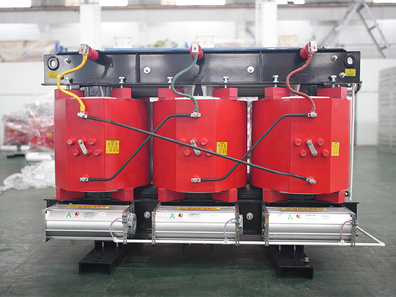
You will choose between two primary structural designs when selecting a dry-type transformer for your facility. Manufacturers build these systems using distinct manufacturing methods and winding enclosure styles.
Cast Resin Transformers
Cast resin transformers feature total encapsulation of their core coils. Manufacturers place the coil windings into a specialized mold inside a vacuum chamber. Liquid epoxy resin fills the mold under vacuum pressure. This resin hardens into a solid, void-free block that encloses the electrical windings completely.
Structural Feature | VPI Transformers | Cast Resin Transformers |
|---|---|---|
Winding Enclosure | Coated and saturated with varnish | Completely encapsulated in a solid block |
Manufacturing Method | Impregnated with varnish under vacuum and pressure | Molded with epoxy resin under vacuum |
Final Physical State | Varnish-coated windings | Solid resin block enclosing windings |
This solid construction gives you significant mechanical and environmental advantages. The solid epoxy shield offers robust protection against severe short-circuit forces and mechanical stress. You can safely operate these units in harsh environments with high humidity, condensation, dust, or corrosive airborne chemicals. Cast resin designs eliminate oil leakage risks, minimize operational vibrations, and ensure long-term stability in demanding industrial settings.
Vacuum Pressure Impregnated Units
Vacuum Pressure Impregnated (VPI) units use a different protective approach. Workers apply a protective polyester or epoxy varnish over the open coil windings inside a vacuum and pressure chamber. The initial deep vacuum phase removes trapped air and moisture from tiny insulation gaps. Next, high pressure forces the liquid varnish deep into all component layers.
This thorough impregnation process drastically improves your transformer's electrical reliability. Filling microscopic air gaps removes structural weak points where electrical discharges typically begin. The process prevents corona discharges, stops electrical tracking, and substantially increases overall dielectric breakdown voltage strength.
You can install VPI transformers in controlled indoor facilities requiring dependable power distribution. These units suit commercial structures, chemical processing plants, mining operations, and large construction projects. You gain efficient cooling, minimal fire hazards, and reduced maintenance costs across your power network.
Key Advantages and Power Ratings
You gain significant operational safety when you select a 3 phase dry type transformer for your building. Ventilated units run without flammable liquid coolants. This design eliminates oil-leak hazards and drastically improves indoor fire protection.
Fire Safety and Low Maintenance
Indoor electrical standards mandate strict fire safety protocols. NEC 450.21 requires proper room ventilation and safe clearance boundaries around your equipment. These physical boundaries prevent operational heat from igniting surrounding structural materials. Industry standards like IEEE C57.12.01 and CSA C9 set explicit performance metrics to ensure indoor safety. Transformers with an F1 fire behavior rating provide self-extinguishing capabilities while limiting toxic fumes during severe thermal events.
Maintenance Aspect | Dry-Type Transformers | Oil-Filled Transformers |
|---|---|---|
Routine Tasks | Periodic visual checks and surface cleaning | Semi-annual visual checks and seal inspections |
Testing & Analysis | None required | Annual or semi-annual fluid testing and Dissolved Gas Analysis |
Fluid Handling | N/A (No liquid medium used) | Fluid filtration every 2–5 years; replacement every 10–15 years |
Service Intervals | Extended periods between servicing | Frequent scheduled maintenance intervals |
Labor & Upkeep Cost | Minimal ongoing operational expenses | Increased maintenance labor costs over lifetime |
Voltage Conversion and kVA Range
General-purpose ventilated transformers feature self-cooling, two-winding configurations. These systems typically operate within nominal power ratings from 15 kVA to 7500 kVA. You can accurately size your equipment to handle continuous electrical loads safely.
Calculate Baseline kVA: Compute your core load requirement using the formula
kVA = (Amps x Volts x 1.732) / 1,000. Convert real power demand in kilowatts usingkVA = kW / PFbefore adding margins.Include Safety Margin: Multiply your calculated baseline by a safety factor of 1.25 to handle future load growth. Size unbalanced three-phase configurations using the peak demand from your highest-loaded individual phase.
Select Transformer Rating: Round your final calculated value up to the next available standard kVA size rather than rounding down.
Applications and Oil Comparison
Indoor and Industrial Applications
You can safely install a 3 phase dry type transformer inside modern facilities with high human occupancy. Critical infrastructure relies on this technology to maintain safe, uninterrupted power distribution:
Enhanced Safety and Fire Protection: Features like cast resin design eliminate oil leakage completely. They significantly reduce fire risks through self-extinguishing and non-explosive properties, meeting strict safety requirements in hospitals and airports.
Clean and Environmentally Suitable: Operating without liquid coolants preserves clean environmental conditions inside sensitive data center operations.
You situate these units directly inside standard electrical rooms next to main load distribution units. Lower overall setup expenses simplify your facility planning and installation process. You avoid fluid containment basining, leak control apparatus, and dedicated environmental safeguards. This direct indoor placement minimizes physical footprint requirements and reduces assembly labor substantially.
Dry Type vs Liquid Filled Units
You must evaluate initial purchase prices alongside lifetime operational expenses when selecting power equipment. Liquid-immersed designs feature lower initial purchase prices. However, indoor liquid installation mandates specialized fire protection systems, secondary containment structures, or specialized high-flashpoint fluids to comply with strict indoor building codes.
Cost Category (1,000 kVA) | Oil-Immersed Transformer | Dry-Type Ventilated Transformer | Dry-Type Cast Resin Transformer |
|---|---|---|---|
Purchase Price | $8,000 – $15,000 | $14,000 – $22,000 | $18,000 – $28,000 |
Indoor Installation Cost | $15,000 – $50,000 | $2,000 – $5,000 | $2,000 – $5,000 |
25-Year Maintenance Cost | $10,000 – $19,000 | $3,750 – $7,500 | $3,750 – $6,250 |
Decommissioning Cost | $3,000 – $8,000 | $1,500 – $3,000 | $1,500 – $3,000 |
Electrical efficiency performance varies between transformer types. A 1,000 kVA oil-immersed unit exhibits 1.0 – 1.2 kW no-load loss and 9.0 – 10.0 kW load loss. A 1,000 kVA dry-type unit exhibits 1.2 – 1.5 kW no-load loss and 11.0 – 13.0 kW load loss. Higher baseline energy losses generate $15,000 – $20,000 higher electricity costs per excess kW over a 20-year cumulative loss impact. Still, dry systems eliminate fluid leakage risks, demand no spill containment trays, and simplify end-of-life decommissioning.
A 3 phase dry type transformer provides superior fire safety, low maintenance costs, and clean environmental performance for modern facilities. These units eliminate oil leak hazards completely. They play a crucial role in indoor power distribution across commercial buildings, industrial plants, and institutional facilities.
Facility managers and electrical engineers must assess specific operational needs carefully during early project planning. You should evaluate your exact primary voltage requirements, secondary voltage requirements, thermal insulation classes, and required kVA ratings before purchasing equipment. Choosing the correct transformer design guarantees maximum operational safety, optimal energy efficiency, and long-term system reliability for your entire facility power network.
FAQ
Why should you choose a dry-type transformer over an oil-filled transformer for indoor use?
You eliminate liquid leak risks and severe fire hazards inside your building. Dry-type units rely on air circulation and solid insulation materials. This design meets strict indoor safety standards like NEC 450.21 without requiring expensive fluid containment basins or specialized fire suppression systems.
What is the difference between VPI and cast resin transformers?
VPI transformers use open coils impregnated with protective varnish under pressure. Cast resin transformers completely encapsulate windings inside solid epoxy blocks. You should select cast resin units for harsh, high-humidity environments and choose VPI units for standard indoor power distribution.
How do you cool a 3 phase dry type transformer?
You can cool these units through natural air convection (AN) or forced air cooling (AF). Natural air circulation cools internal components passively during standard operation. Activating forced air fans pushes cooling air directly over core windings, which increases continuous load capacity by roughly 33%.
What power ratings are available for general-purpose dry-type transformers?
You can select standard general-purpose ventilated transformers with power ratings ranging from 15 kVA to 7500 kVA. You calculate your load needs, apply a 1.25 safety factor, and round up to the next standard rating to protect against future power spikes.


